Performance (MMANA-GAL / OK1M-PyminiNEC3)
Computed at 12 m height over real ground (ε = 13, σ = 5 mS/m), horizontal polarization, model v0.4.
| Band | Elements | Frequency | Gain | F/B | SWR | Elevation | SWR < 1.5 | SWR < 2 |
|---|---|---|---|---|---|---|---|---|
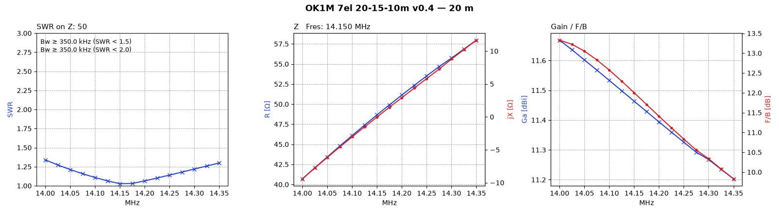
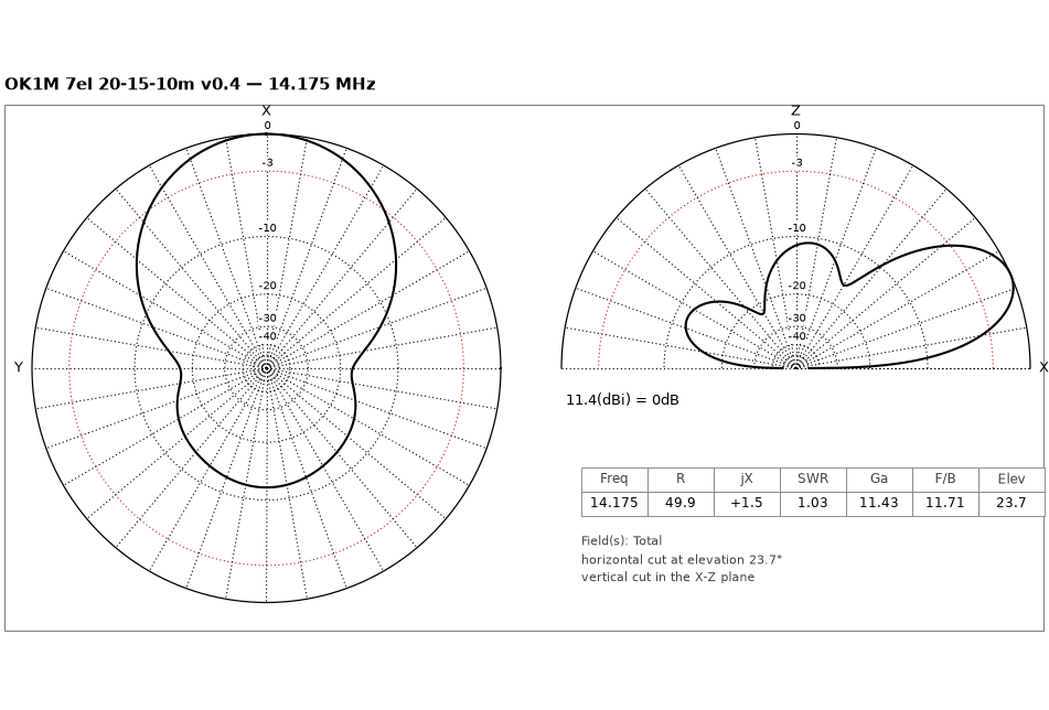
| 20 m | 2 | 14.175 MHz | 11.4 dBi | 11.7 dB | 1.03 | 23.7° | whole band | whole band |
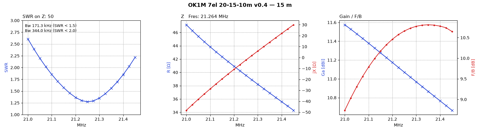
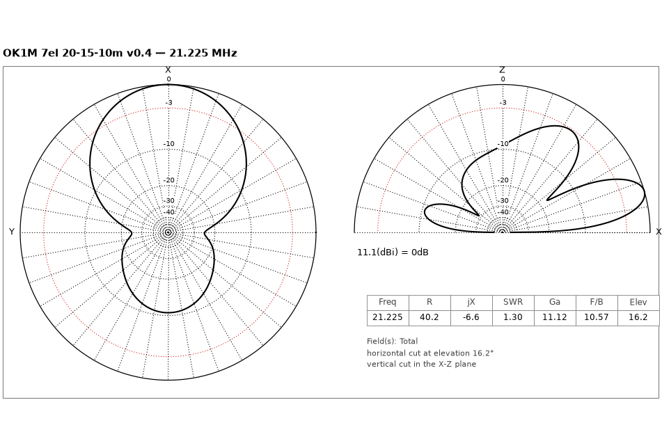
| 15 m | 2 | 21.225 MHz | 11.1 dBi | 10.6 dB | 1.30 | 16.2° | 171 kHz | 344 kHz |
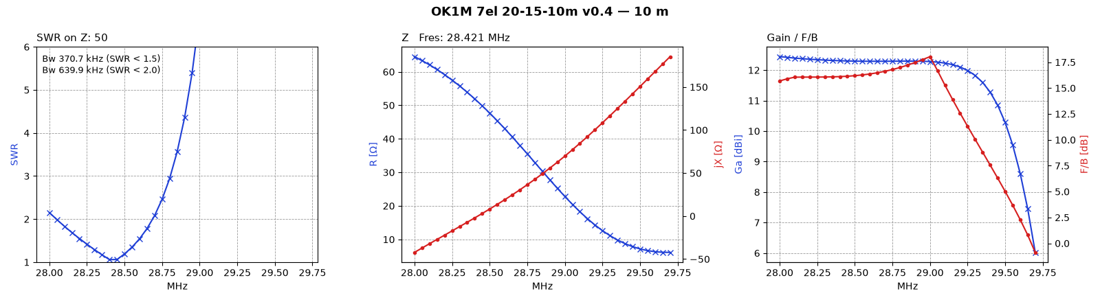
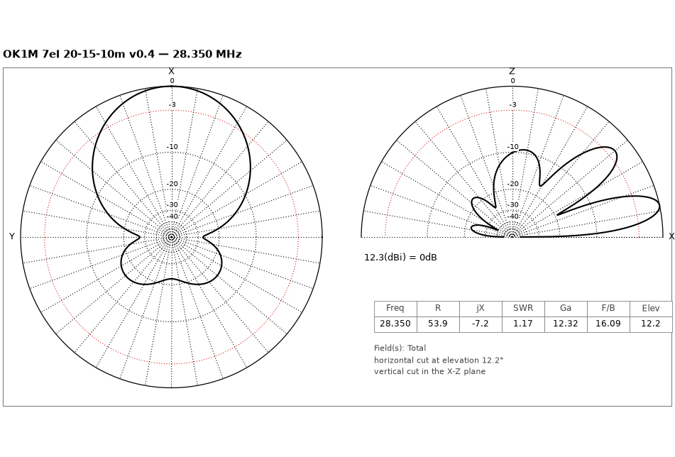
| 10 m | 3 | 28.350 MHz | 12.3 dBi | 16.1 dB | 1.17 | 12.2° | 371 kHz | 640 kHz |
| Band | Range | SWR | Gain | F/B |
|---|---|---|---|---|
| 20 m | 14.000–14.350 | 1.03–1.34 | 11.2–11.7 dBi | 9.8–13.3 dB |
| 15 m | 21.000–21.450 | 1.27–2.61 | 10.7–11.6 dBi | 8.7–10.8 dB |
| 10 m | 28.000–28.700 | 1.06–2.15 | 12.3–12.4 dBi | 15.7–16.6 dB |
v0.3 introduced lighter 15 m elements (Ø20 centre + Ø16 tips instead of Ø25/20/16) with the REF 15m and DE 15m lengths and positions retuned. The thinner 15 m tubes cost a little bandwidth: SWR < 2 over 21.078–21.422 MHz, 2.6 / 2.2 at the band edges.
Computed with OK1M-PyminiNEC3 (MININEC 3 core). v0.4 was re-computed in MMANA-GAL pro: over 14 points across the three bands the two agree to R ±0.1 Ω, jX ±0.2 Ω, Ga ±0.04 dB, F/B ±0.14 dB, with the same segmentation (333 pulses at 28.5 MHz).
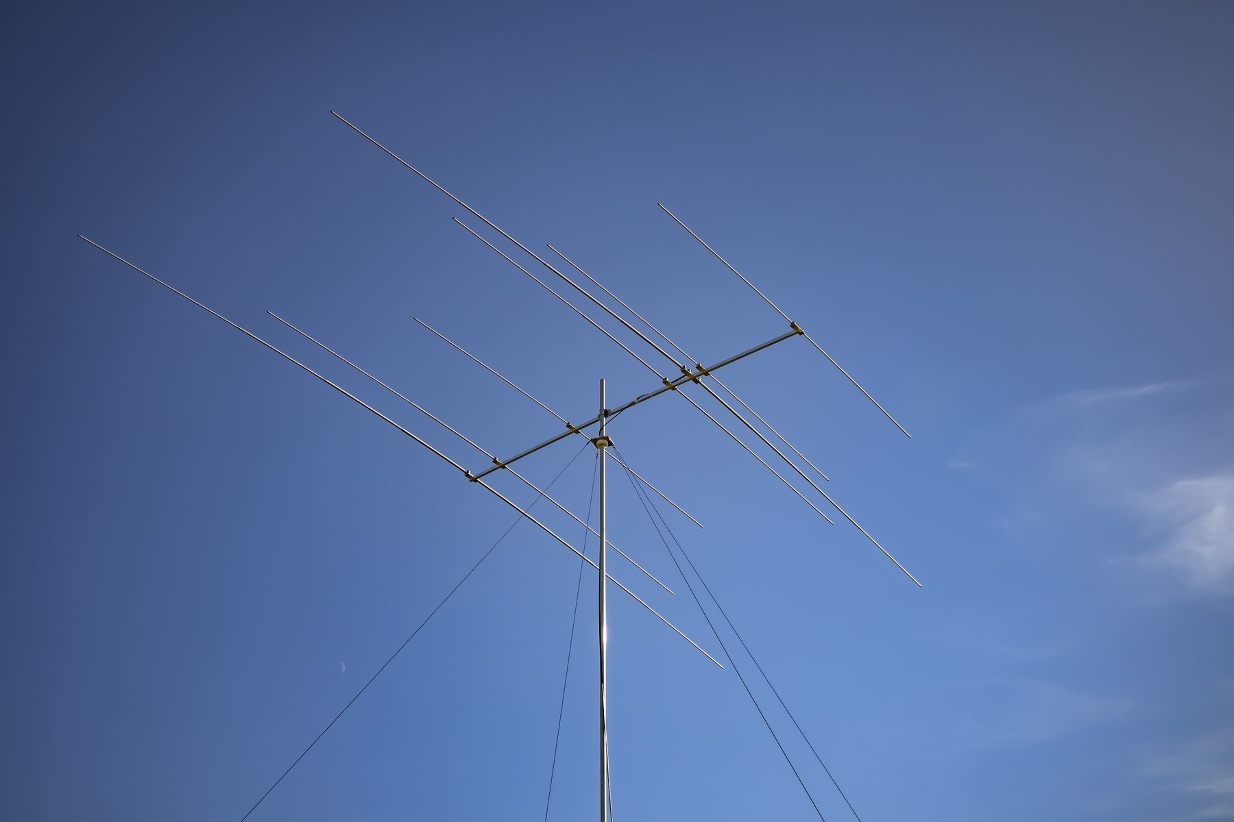
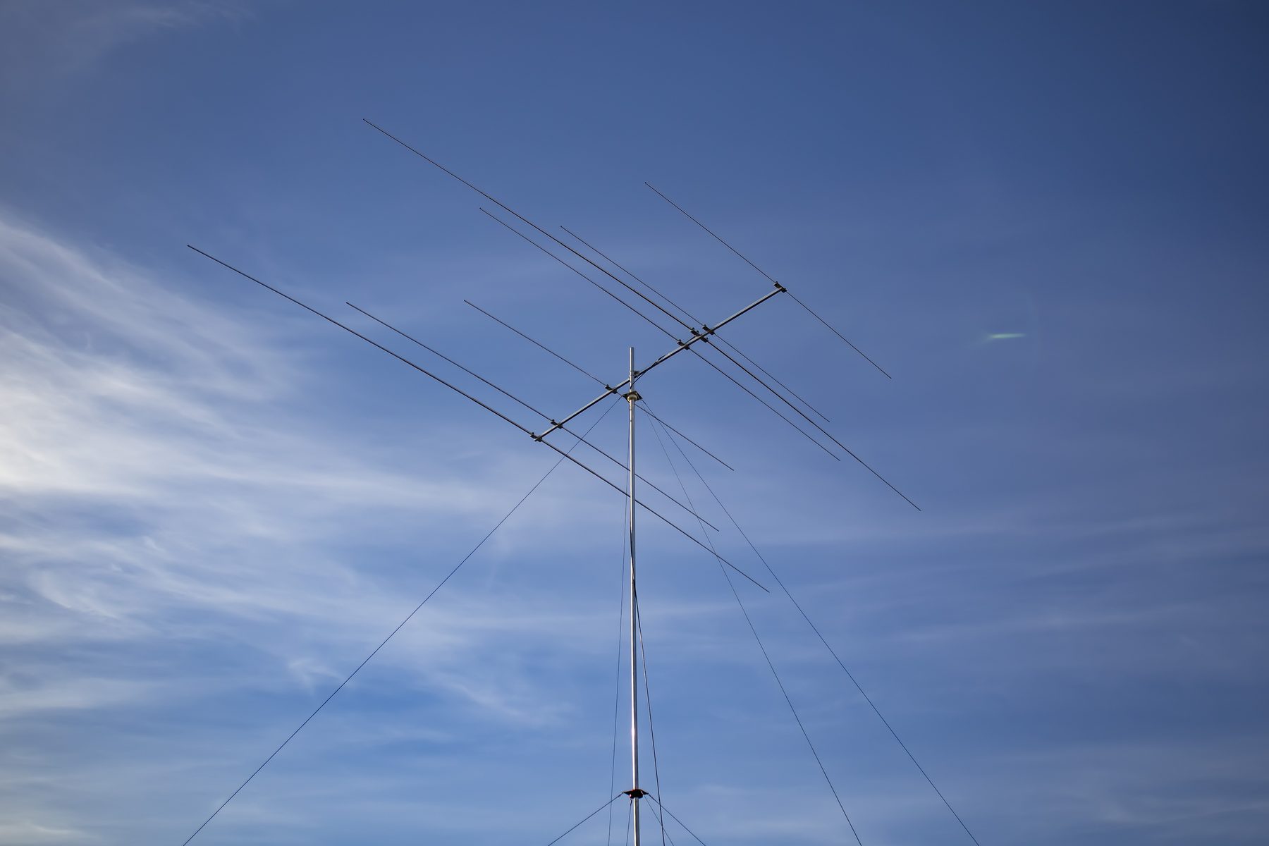
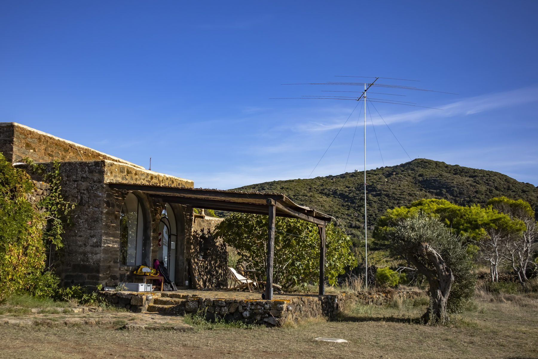
Built: Pantelleria, CQ WW DX SSB 2026
The first antenna built to this design was assembled on site on Pantelleria (JM56) in October 2026 and worked the contest as IH9/OK1M. All seven elements went together from the cut list below without changes to the model dimensions.
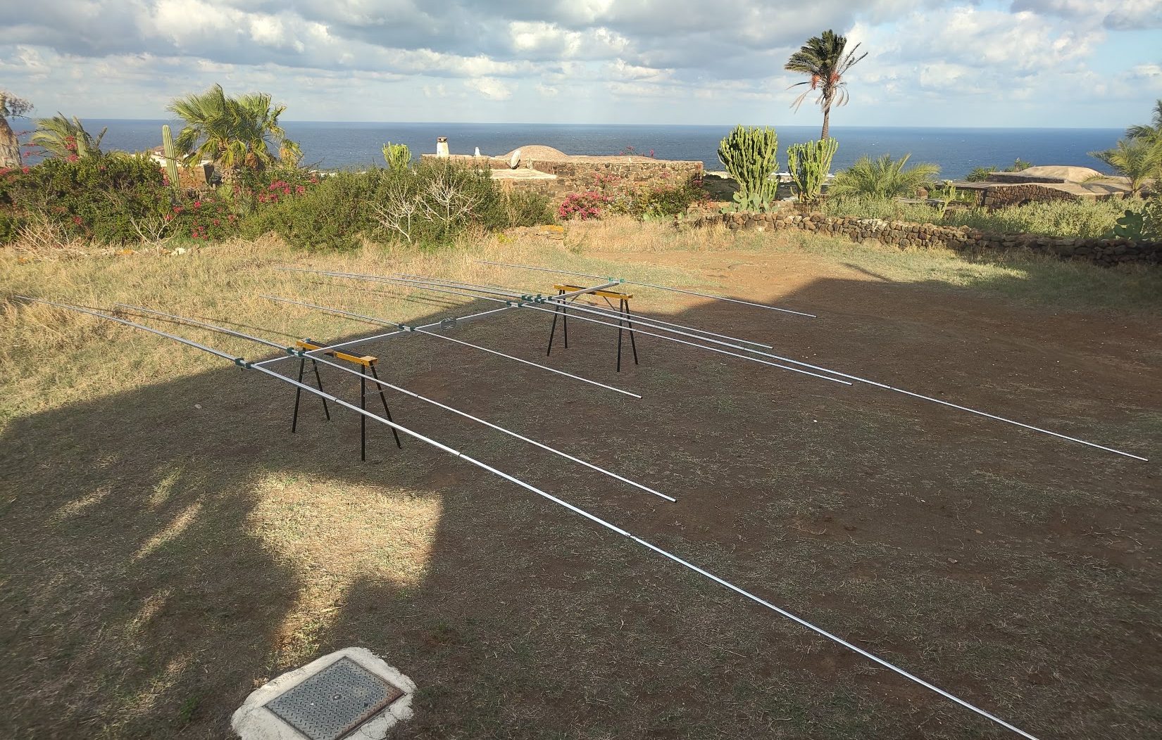
Assembly
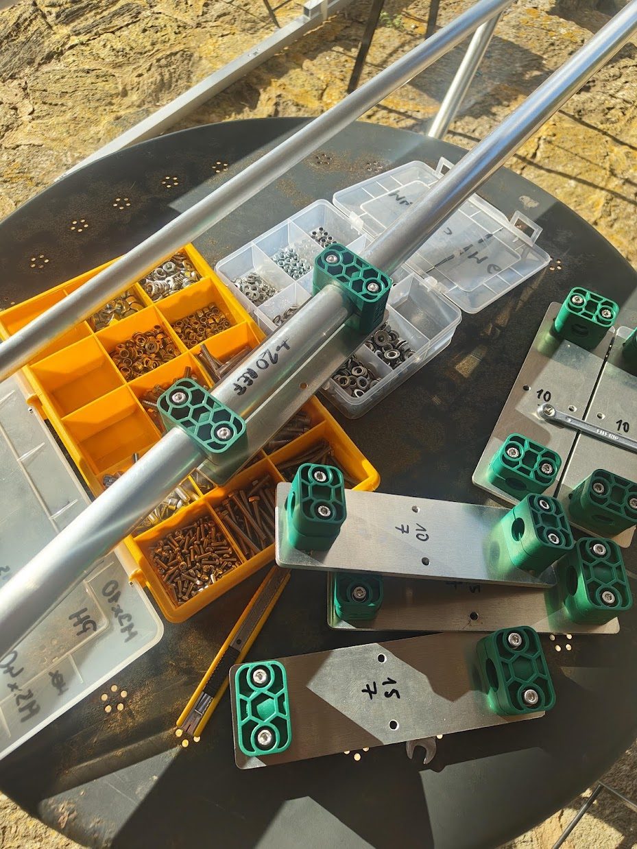
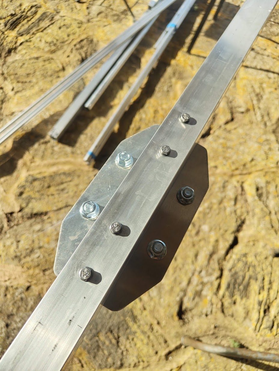
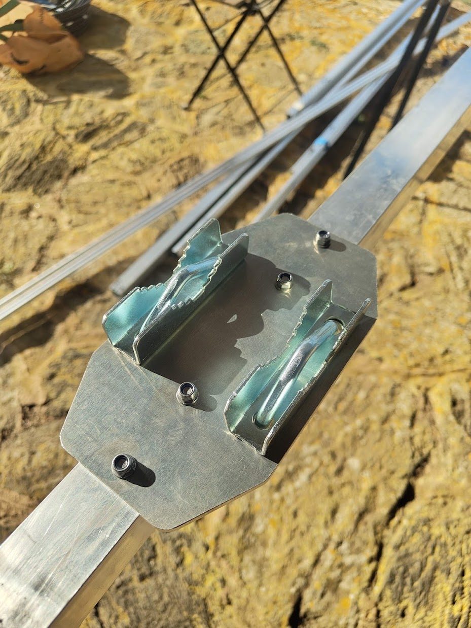
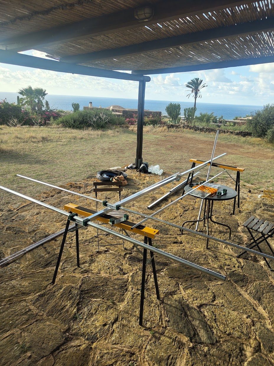
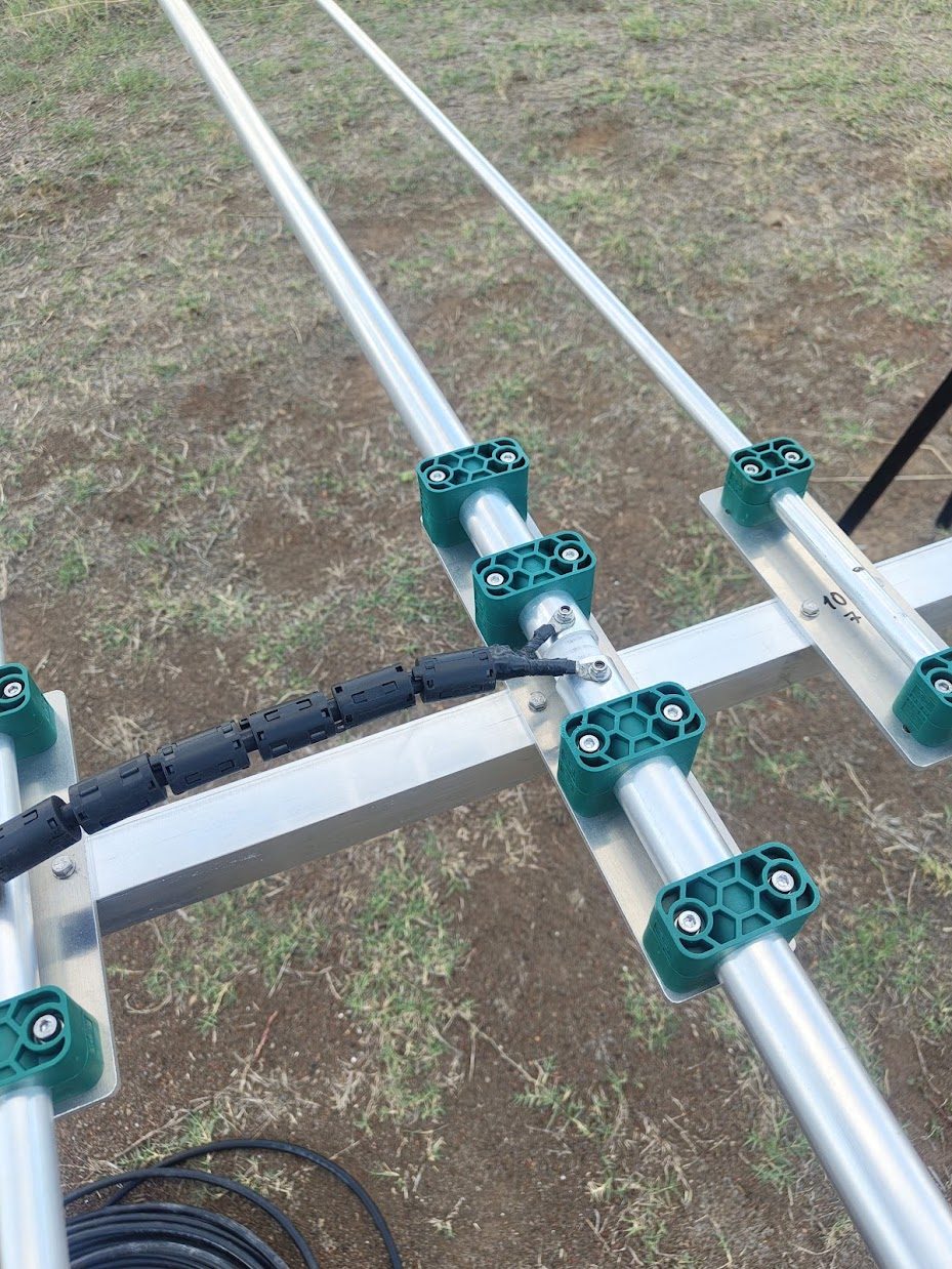
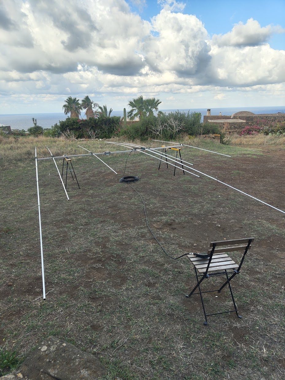
On the mast
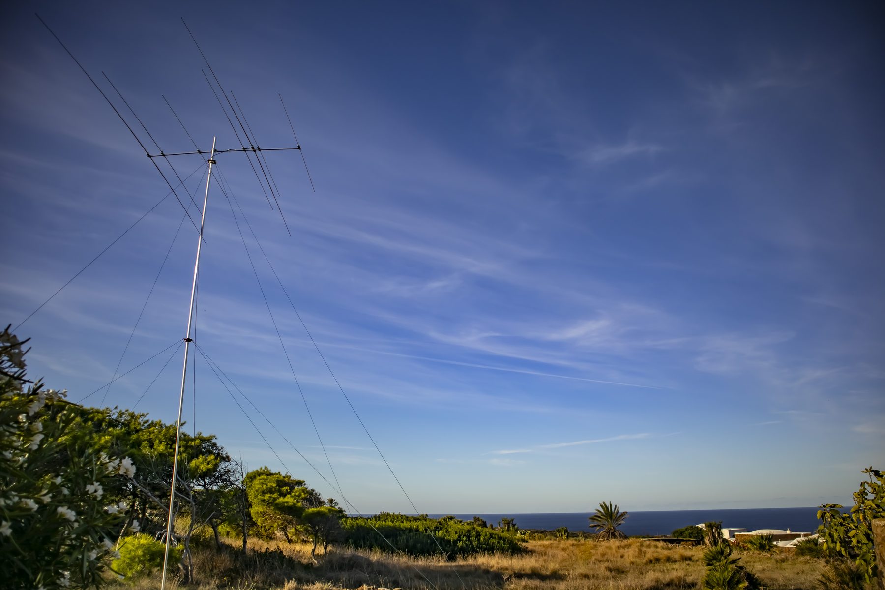
Elements
Position is measured from REF 20 m (MMANA X from DE 20 m in brackets) and from the rear end of the boom. Lengths are the total tip-to-tip element length (model v0.4 rounded to mm).
| Element | Band | Pos. from REF 20 m | From DE 20 m | From boom rear end | Length | Half | Tubes |
|---|---|---|---|---|---|---|---|
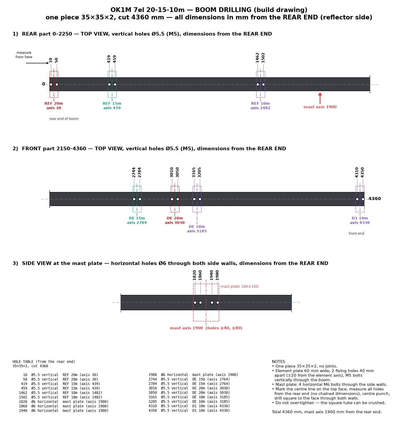
| REF 20m | 20 m | 0 | −3 000 | 30 | 10 974 | 5 487 | 30 / 25 / 20 / 16 |
| REF 15m | 15 m | 409 | −2 591 | 439 | 7 130 | 3 565 | 20 / 16 |
| REF 10m | 10 m | 1 452 | −1 548 | 1 482 | 5 198 | 2 599 | 16 |
| DE 15m | 15 m | 2 734 | −266 | 2 764 | 6 846 | 3 423 | 20 / 16 |
| DE 20m (feed) | 20 m | 3 000 | 0 | 3 030 | 10 294 | 5 147 | 30 / 25 / 20 / 16 |
| DE 10m | 10 m | 3 155 | +155 | 3 185 | 5 166 | 2 583 | 16 |
| D1 10m | 10 m | 4 300 | +1 300 | 4 330 | 4 788 | 2 394 | 16 |
Element design — Al tubes
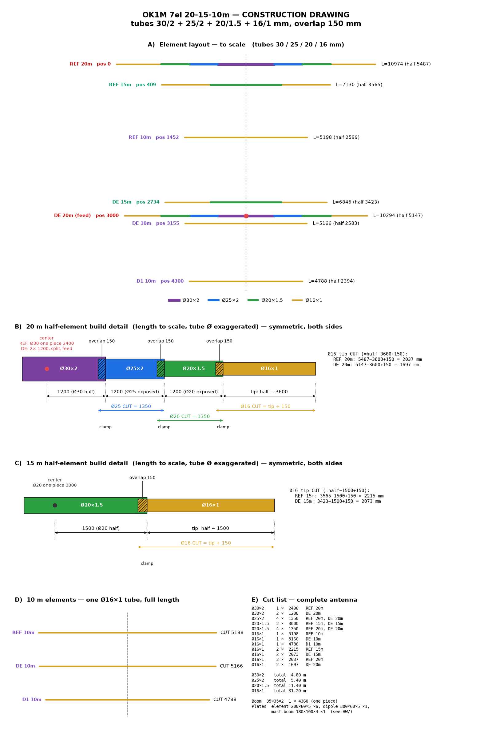
Telescopic tubes, overlap 150 mm in every joint. Visible lengths measured from the boom axis:
| Band | Center | 2nd tube | 3rd tube | Tip |
|---|---|---|---|---|
| 20 m | 30/2 — 2 × 1 200 (one piece 2 400) | 25/2 — 1 200 (cut 1 350) | 20/1.5 — 1 200 (cut 1 350) | 16/1 — half − 3 600 (+150) |
| 15 m | 20/1.5 — 2 × 1 500 (one piece 3 000) | 16/1 — half − 1 500 (+150) | ||
| 10 m | 16/1 — one tube, full length |
DE 20 m is split in the center (2 × 30/2 1 200 mm) and mounted insulated on the dipole plate — this is the only feed point. DE 15 m and DE 10 m are continuous elements (open sleeve) coupled from DE 20 m.
Joints: slot the end of the outer tube and secure with a stainless hose clamp. Tip lengths are cut as listed; final trimming is done during SWR tuning.
Boom
- One piece 35×35×2 mm, 4 360 mm — no joints, 30 mm overhang past the outer elements (cut from a 6 m bar).
- Boom mass 3.1 kg — lighter than a stepped 30/35/30 boom (3.5 kg incl. the 325 mm joint overlaps), with the same max. static bending stress (approx. 38 MPa at the mast).
- Mast plate at the computed center of gravity 1 900 mm from the rear end (1 130 mm behind DE 20 m) — check by balancing the finished antenna before final tightening.
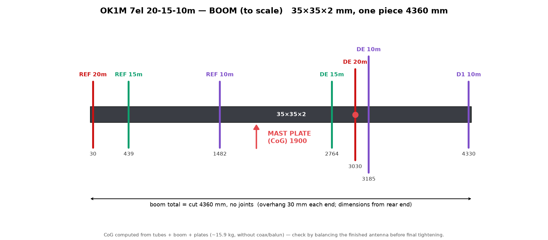
Construction drawing — elements
Cut list
Element tubes
| Tube | Qty | Length | Used in |
|---|---|---|---|
| 30/2 | 1 | 2 400 | REF 20m |
| 30/2 | 2 | 1 200 | DE 20m |
| 25/2 | 4 | 1 350 | REF 20m, DE 20m |
| 20/1.5 | 2 | 3 000 | REF 15m, DE 15m |
| 20/1.5 | 4 | 1 350 | REF 20m, DE 20m |
| 16/1 | 1 | 5 166 | DE 10m |
| 16/1 | 1 | 5 198 | REF 10m |
| 16/1 | 1 | 4 788 | D1 10m |
| 16/1 | 2 | 2 215 | REF 15m |
| 16/1 | 2 | 2 073 | DE 15m |
| 16/1 | 2 | 2 037 | REF 20m |
| 16/1 | 2 | 1 697 | DE 20m |
Total tube length
| 30/2 | 4.80 m |
| 25/2 | 5.40 m |
| 20/1.5 | 11.40 m |
| 16/1 | 31.20 m |
Boom
| 35×35×2 | 1 × 4 360 (one piece) |
Plates
| Element plate 200×60×5 | 6 |
| Dipole plate 300×60×5 | 1 |
| Mast-boom plate 180×100×4 | 1 |
| Clamp RAP430X (Ø30, A4) | 6 |
| Clamp RAP220X (Ø20, A2) | 4 |
| Clamp RAP216X (Ø16, A2) | 6 |
Plates
Laser-cut aluminium plates (same as the 9el), DXF for cutting and PDF drawings in Downloads.
- Element plate 200×60×5 mm — all elements except DE 20 m; slotted holes for U-bolts of Ø16–30 mm tubes.
- Dipole plate 300×60×5 mm — DE 20 m, two insulated halves.
- Mast-boom plate 180×100×4 mm.
Insulators — tube clamps
Element tubes are held by polypropylene tube clamps DIN 3015-1, light series A (e.g. Parker RAP…X), which also insulate the elements from the plates. Two clamps per element plate (160 mm apart), four on the dipole plate. The bolt distances match the slotted holes of the element plate.
| Tube | Clamp | Size | b × c × width | Bolt distance | Qty | Elements |
|---|---|---|---|---|---|---|
| Ø30 | RAP430X | A4 | 59 × 42 × 30 | 40 | 6 | REF 20m (2), DE 20m (4) |
| Ø20 | RAP220X | A2 | 42 × 33 × 30 | 26 | 4 | REF 15m, DE 15m |
| Ø16 | RAP216X | A2 | 42 × 33 × 30 | 26 | 6 | REF 10m, DE 10m, D1 10m |
Bill of materials
Complete parts list for one antenna (model v0.4). Mass approx. 15.9 kg without coax and balun. Element tube cut lengths are in the cut list.
Order — Al stock bars 6 m (EN AW-6060 / 6063 T6)
| Profile | Bars | Cutting plan (kerf ~3 mm) | Offcut |
|---|---|---|---|
| Ø30×2 | 1 | 2 400 + 1 200 + 1 200 | ~1 190 |
| Ø25×2 | 1 | 4 × 1 350 | ~590 |
| Ø20×1.5 | 2 | each bar 3 000 + 2 × 1 350 | 2 × ~290 |
| Ø16×1 | 6 | 5 198 / 5 166 / 4 788 / 2 × (2 215 + 2 073 + 1 697) / 2 037 + 2 037 | 802, 834, 1 212, ~1 920 |
| □35×35×2 | 1 | 4 360 (boom, one piece) | ~1 640 |
Plates, insulators, hardware
| Part | Qty | Used for |
|---|---|---|
| Element plate 200×60×5 (Al, laser cut) | 6 | all elements except DE 20m |
| Dipole plate 300×60×5 | 1 | DE 20m |
| Mast-boom plate 180×100×4 | 1 | mast |
| Clamp RAP430X (Ø30, A4) | 6 | REF 20m (2), DE 20m (4) |
| Clamp RAP220X (Ø20, A2) | 4 | REF 15m, DE 15m — check type in the catalogue |
| Clamp RAP216X (Ø16, A2) | 6 | REF 10m, DE 10m, D1 10m |
| Bolt M5×55 A2 | 12 | Ø30 clamps |
| Bolt M5×45 A2 | 20 | Ø20 and Ø16 clamps |
| Bolt M5×50 A2 | 14 | plates to the boom (vertical) |
| Bolt M6×50 A2 | 4 | mast plate to the boom (horizontal) |
| Bolt M5×40 A2 + ring cable lug M5 | 2 | feed terminals DE 20m |
| Self-locking nut M5 / M6 | 48 / 4 | |
| Washer M5 / M6 | 80 / 8 | |
| U-bolt M8 with nuts and washers | 2 | mast clamp — choose for the mast diameter |
| Hose clamp W4 9 mm, 25–40 / 20–32 / 16–27 | 4 / 4 / 8 | joints 30/25, 25/20, 20/16 |
| End cap Ø16 / Ø30 / □35 | 14 / 2 / 2 | element tips, DE 20m inner ends, boom ends |
| Contact grease for Al joints | 1 | all telescopic joints |
| 1:1 current balun 50 Ω | 1 | DE 20m feed point |
| Coax 50 Ω, UV-resistant cable ties | — | as needed |
SWR and field diagrams
Model v0.4, 12 m above real ground, computed with OK1M-PyminiNEC3 (MMANA-GAL pro conventions).
The patterns are a replica of the MMANA-GAL pro “Plots → Far fields” window (radial scale r/R = 10dB/40, rings −3 / −10 / −20 / −30 / −40 dB) and show the total field; the Ga and F/B figures are for horizontal polarization.
20 m
15 m
10 m
Downloads
- OK1M-7el-20-15-10m_v0.4.maa — MMANA-GAL model v0.4, REF 10m 5 198 mm, verified in MMANA-GAL pro (this page)
- OK1M-7el-20-15-10m_v0.3.maa — MMANA-GAL model v0.3, REF 10m 5 100 mm
- OK1M-7el-20-15-10m_v0.2.maa — MMANA-GAL model v0.2, 15 m elements 25/20/16 mm, verified in MMANA-GAL pro
- Bill of materials — complete parts list, also
BOM.mdin the repository - boom.png, boom_drilling.png, build.png — construction drawings
- element.dxf, element.pdf — element plate 200×60×5
- dipole.dxf, dipole.pdf — dipole plate 300×60×5
- mast-boom-plate.dxf, mast-boom-plate.pdf — mast-boom plate 180×100×4
- drawings.py — Python script generating the construction drawings
- Git repository — source of all files